The guys at FLI tested my 11002 camera and could not fix it. The vertical stripes seemed to be inherent to the chip :-(
Although, I found ways to correct for the stripes, I'd prefer a camera that doesn't have any artifacts. After a little bit of research, I decided on the 16070 chip (also from Kodak). Greg at FLI was a little bit concerned that this chip would have similar artifacts (apparently both chips have a very similar architecture). But he offered to lend me a camera with that chip, so that I can try it out.
It arrived yesterday - and so did the rain :-( So, I started my evaluation just with flats. With the 11002 chip, I could see the vertical strips pretty clear at shorter exposures:
0.001 sec:
0.01 sec:
0.1 sec:
1 sec:
10 sec:
Well, so far so good. Now I have to wait for clear skies to take some real images.
Astrophotography combines some of my major passions in life: mathematics, astronomy, computers ... and buying gadgets!
Saturday, March 29, 2014
Sunday, March 16, 2014
Using Robofocus Server instead of Ascom?
By chance I noticed an entry in the SGP focuser dropdown focuser box called "Robofocus Server". I read up on it and it turns out that this is an alternative way to drive the Robofocus focuser. Instead of creating and Ascom interface, this driver starts the Robofocus control program and uses that. One big advantage is that this driver supports reading the temperature sensor of the Robofocuser unit.
As I found out previously, the Robofocuser unit does not work with the Serial-USB adapters with the captive port. So, I used one of the cheap ones (which does not retain its port number) and it works beautifully: connects, controls and reads the temperature.
One weird thing is that the temperature is 100*Celsius...
For now, I will just use the Robofocus Server for focusing, but keep using the TEMPerHum device for temperature reading - then I won't have to recalibrate my temperetaure/focuser coefficient. If it works, then I should try to find a Serial-USB adapter with a captive port that works with the unit and ultimately might be able to get rid of one device.
Or is it better to have another device, but one program less running on my laptop?
Monday, March 3, 2014
Oscillating RA axis
In my last imaging sessions, the RA axis was heavily oscillating:
(the corrections aren't correctly plotted. They were in fact down, when the mount was too far up).
I moved the counterweight such that the scope becomes east-heavy. But that didn't change anything. I wonder if this means that I will have to remesh my RA gears. I posted on the ap-gto mailing list and got some good feedback:
I moved the counterweight such that the scope becomes east-heavy. But that didn't change anything. I wonder if this means that I will have to remesh my RA gears. I posted on the ap-gto mailing list and got some good feedback:
- Several folks asked if this is this REALLY the RA axis and not the DEC axis? I'm almost 100% sure, but will check next time.
- It's unlikely that this is the result of backlash, i.e. remeshing the gears won't help.
- Check if oscillations only happen with then scope is targeted towards the zenith or also in other positions.
- Because the mount needs a couple of small corrections, it could be that some cable is getting stuck or such. The mount needs too many corrections to overcome this additional resistance - and then shoots over. Will check that - and also if they aren't getting stuck somewhere inside the mount.
- Bad callibration. One suggestion was to set aggressiveness to 0%, then 30%, then 60% then 100% ("Oscillations in RA are super rare and only occur if the loop gain is larger than 100% - caused by improper cal run.")
- Sanity checking my PHD2 calibration:You can also sanity check your calibration using the PHD2 log file. Before a guiding sequence begins, there will be a block of text in the log that starts with "Guiding Begins" Look below that line for values of xRate and yRate, which are RA and Dec rates respectively. The numbers there are in units of pixels/millisecond. Also in that text block, you should find a value of your image scale (arc-sec/pixel) assuming you have configured that in PHD2. So taking the yRate * 1000 * image scale, you will get the Dec rate in units of arc-sec/sec - and you can compare this with sidereal rate, which is 15 arc-sec/sec for declination. If you are guiding at 1x sidereal, your computed Dec rate should be pretty close to 15 in other words. You can do the same for the RA rate, but you need to remember that the RA rate will be affected by the declination at which you do the calibration. You would divide the xRate number by cos(declination) to get an equivalent value.
---
- So, first thing I checked was if this was really the RA axis. I guided and pushed on the keypad the west and easy arrow. And sure enough what PHD designated as RA went sharp up / down.
- Next, I checked all my cables. Couldn't find anything at first. But then I realized that I recently started to leave the RAPAS in the mount and that squeezed the USB and power cable that run through the mount. So, I removed the RAPAS and it went better. But after a while the oscillations were back.
- Then I played with the calibration parameters. When I set Aggressiveness to 100 and Hysteresis to 0, then the mount was sort of able to compensate.
- Finally, I checked how the mount tracks without any guiding:
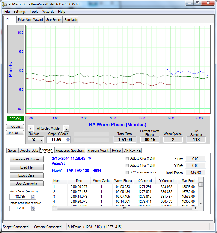
- Well, that does not look good. Somehow the mount itself creates these oscillations with an amplitude of 10+" and a frequency of ~7 minutes. And that is very hard to guide out.
- I remeshed my gears - no change.
I took a PEM analysis:
You can see the larger error: 7.53" peak-to-peak. But at least it's periodic, so with PEC it should be possible to make it much smaller. I chose a quadratic curve and measured again:
1.15" peak-to-peak error only!
This should allow me to image the next nights. But it is concerning that this mount shows such a large periodic error.
Sunday, March 2, 2014
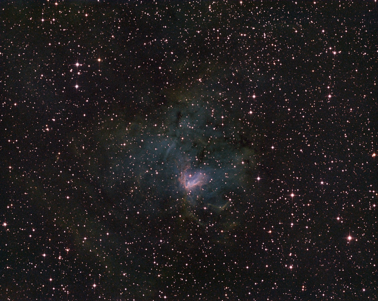
NGC 1491
NGC 1491 is an emission nebula in Perseus. It's 10,700 light years away in the Perseus arm of the Milky Way. Stars are created in this nebula - and the ultraviolet light from those newborn stars excite the atoms of the nebula - which makes it glow.
Click on the image for more details on capturing this image.
I did not have enough time to capture more SII (red) data. But with a lot of processing (see below), I could bring out quite some detail. Here is the core part of the nebula:
Some nice detail, but it shows that this image could use more data to increase the SNR.
Because this object turned out to be rather faint, I really had to stretch my post processing skills on this one:
- I calibrated, stacked and aligned the images in CCDStack and cropped them.
- Then I neutralized the background of all 3 images
- I combined them by summing them up for a synthetic luminance image
- Deconvolved this image
- Stored all of them (scaled) as TIFF's
- Then, I used Straton to create a star-only image of the synthetic luminance image.
- Loaded the SII, Ha and OIII images in Photoshop and used a tutorial by Paul Kanevsky for DDP (Digital Development Processing) in Photoshop (unfortunately, the action that Paul made out of his tutorial does not work in Photoshop CS6)
- In Photoshop, I combined the SII, Ha, OIII images as described by Ken Crawford.
- Of each individual image, I "brought out the faint stuff" using a great recipe by Scott Rosen.
- Then I adjusted the levels of each individual image to darken the background
- Adjusted opacity of each layer to get a good mix of all colors (as always the green from Ha was dominant)
- Added a CAB layer and applied GradientXTerminator
- Used a "Selective Color" layer to reduce the amount of magenta (mostly in the stars) and to bring out the orange parts more
- Loaded the synthetic luminance image
- Used an adjustment layer with a mask to reduce the brightness of the core and increased its contrast (see e.g. http://helpx.adobe.com/photoshop/using/masking-layers.html for an explanation)
- Layered the luminance image over the combined image using "Soft Light" mode and adjusted Opacity to find a balance between bringing out details and still showing the fainter parts of the nebula
- Loaded the star-only image and used a simple levels adjustment to remove all nebula remnants (but being careful not as to remove any faint stars)
- Layered this star-only image on top (using Screen mode)
- Finally, I created a CAB layer on top and applied the "Star Diffraction Spikes Fat Stars" from Carboni's Astronomy Tools.
There are so many steps here that I tried for real for the first time. Considering that, I'm pretty happy with the result.
Subscribe to:
Posts (Atom)


